Newer Orbital Implants
Updated July 2024
Indications & Principles for Implant Placement
- Orbital implants are used to restore (or augment) internal and external orbital anatomy, shape, contour and volume
- Internal orbital fractures with resultant orbital volume loss and anatomic disruption are the major indication for orbital implant placement
- Internal orbital fractures result in volume expansion as a result of buckling and compression
- Buckling: Force on rim transmits to thin orbital walls and results in fracture
- Compression: Retropulsion of the globe leads to transiently increased pressure from posterior orbital contents and “blow out” of fracture elements into sinuses
- Additional contributors to anatomic disruption are soft tissue abnormalities
- Intraconal fat displacement
- Distortion or herniation of orbital fat or extraocular muscles
- Disruption of extraocular muscle septations
- Other indications for orbital implants are:
- Reconstruction after cancer resection (e.g. after maxillectomy)
- Secondary repair of incompletely reduced traumatic deformities (e.g. to correct midface depression after a ZMC fracture)
- Augmentation of internal orbital volume (e.g. in the anophthalmic socket)
- Augmentation of the orbital rims (e.g. for midface hypoplasia)
- Orbital implants are not always necessary in orbital fracture repair, e.g.:
- Pediatric “white-eyed blowout fractures”: Flexible, still viable bone springs back into position
- Zygomaticomaxillary complex fractures: Periorbita often remains intact with little disruption in orbital contents after zygoma reduction. Objective in this case is to limit gaps and gross motions between elements, promoting woven bone formation and remodeling into lamellar bone.
- Desirable (“ideal”) implant characteristics:
- Biocompatible
- Low morbidity at any donor site
- Structurally supportive
- Moldable to the orbital contour
- Unlikely to create undesirable local adherence (e.g adherence to the orbital contents or periorbital soft tissues)
- Stability (retains position and continues to provide support over time)
Types of Orbital Implants
- Various implant materials are available, with no gold standard
- Choice of implant is determined by surgeon preference, which often depends on surgeon specialty and geography of practice
- Porous polyethylene with or without embedded titanium has become common among all specialties in the US
- Oculofacial surgeons have typically endorsed usage of more nylon sheets and absorbable plates
- Plastic and Otolaryngology Head and Neck Surgery (OHNS) Facial Plastic surgeons have traditionally preferred uncovered titanium [5, 6]
- Internationally, surgery is more often done by oral maxillofacial surgeons and absorbable plates and bone grafting is more common [7]
- Autografts
- More commonly used internationally [5]
- Split-thickness calvarial grafts (can be harvested at the time of surgery if extensive midfacial trauma), iliac crest and rib common sources
- Allografts
- Metallic
- Titanium is mainstay for screw manufacture and mesh plate design
- Used since the 1960’s
- Good strength and excellent shape retention
- Low profile
- Visible on subsequent radiographs
- High strain tolerance which can be increased with oxygen and by soaking in acid [8]
- Strength can be varied by “condensing” titanium in the posterior orbit, improving strength on load bearing but small elements (e.g. the posterior ledge of an orbital floor fracture)
- Porous
- Hydroxyapatite, Porous polyethylene (PP)
- Biocompatible, well-tolerated
- Used since 1980’s
- Pores allow for fibrovascular ingrowth to limit encapsulation and prevent migration, extrusion and infection
- Pore size can be varied, with small pore size facing orbit to limit adherence and facilitate implant removal if necessary, large pore against orbital floor to increase adherence and reduce movement [3, 9]
- Porous-Metallic Hybrid
- Commonly used
- “PPTe”: Titanium mesh embedded between two layers of PP [e.g. Medpor Titan, Styrker; Synpor Titanium Reinforced, Synthes]
- Adds additional implant shape stability to PP
- Non-metallic, non-porous
- Examples: Nylon sheets [Supramid], Silicone sheets, Sterilized x-ray film [10]
- Inert, cost effective and can mold to the orbital floor well
- Migration and extrusion can be decreased with screw fixation or by deflecting a small tab into the maxillary sinus [11]
- Absorbable materials
- Degrade by hydrolysis over varying amounts of time
- Can be molded to desired shape as the materials relax when heated
- Various iterations in animal models have demonstrated bony encapsulation
- Often cause local tissue inflammation
- Newer devices aim to replace screws with absorbable pins that are set with an ultrasonic vibration [SonicWeld, KLS Martin]
- Examples:
- Polydioxanone (PDS): Very flexible, thin, smooth sheet, degrades in 6 months
- Poly-l-lactide (PLLA): Degrades over 3-5 years, also used to make absorbable screws [Rapidsorb, Synthes]
- Poly-d,l-lactic acid (PDLLA) [Resorb-X KLS Martin]
- Polyglycolide (PGA) co-polymers: E.g. Polylactic Acid/PGA (also known as polyglactin 910 found in Vicryl suture), PLLA/PGA [Lactosorb, Zimmer Biomet]
Patient Specific Implants (PSI's)
- Patient-specific implants refer to:
- Implants that are custom designed for a specific patient; or
- Commercially available implants available in different sizes that are selected specifically for a patient based on their bony anatomy (Figure 1 demonstrates the evolution of titanium embedded porous polyethylene and uncoated titanium implant construction)
- Advances in 3-D modeling, computer-assisted design, rapid prototyping and 3-D printing have led to proliferation of PSI options
- Implants can be directly “printed” in various materials from commercial partners: PP, polyether ether ketone (PEEK) and titanium (Figure 2)
- Printing times vary but a sterilizable implant is delivered for intraoperative use
Figure 1: Evolution of internal orbital implants.
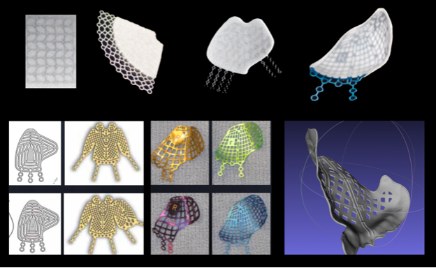
Top row: Advancements in porous polyethylene. From left to right: Embedded titanium mesh, 2-D fan shaping, more complex 2-D shaping, 3-D preformed anatomic plate. Bottom row: Advancements in uncoated titanium implants. From left to right: Small and large KLS and Biomet 2-D implants, Synthes and Stryker 3-D preformed anatomic plates, 3-D printed patient specific titanium implant.
Figure 2: Example of a 3-D titanium, 3-D Polyether Ether Ketone (PEEK) implants.
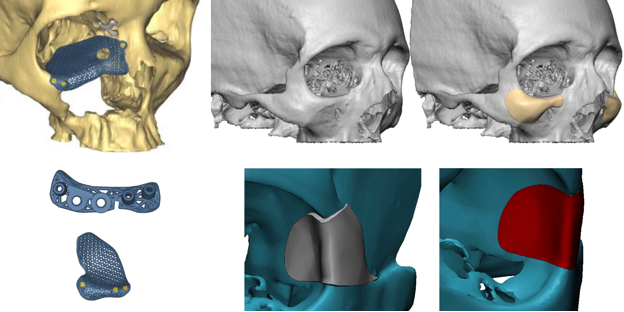
Lower left: see associated drill guide and a cutting guide for an osteotomy.
Concepts, Workflows and Techniques Important to PSI Design and Implementation
- Concept: Virtual Modeling
- High quality CT scan (< 1mm axial slice thicknesses) → Bony anatomy extracted using a technique called segmentation based on CT Hounsfield units → Virtual model of bony anatomy is created
- Smoothing and interpolation can be used to improve fidelity as thin orbital bones may not appear completely; this can be done by standard computer-aided design (CAD) programs (e.g. MeshLab) or using auto-segmentation algorithms in medical CAD programs (e.g. iPlanENT from Brainlab, Materialise)
- In cases of unilateral pathology such as trauma, mirroring can be used to create a target model based on the unaffected side
- If mirroring is not an option, virtual modeling is still possible using virtual standardized orbital models that can be shaped
- Workflow: 3-D Printed Mold for Surgeon Implant Bending
- Once a virtual model of the bony anatomy created, a target mold can be 3-D printed and a generic titanium or PP implant can be manually shaped to fit the mold by the surgeon (Figure 3)
- Commercial medical device manufacturers can produce institution approved sterilizable molds (usually in clear acrylic) and assist in the design process
- Commercially provided skulls are pictured in Figure 5 and 6, though these were not used for manual plate bending in the cases shown
- Alternatively, the mold can be produced by a commercial rapid prototyping partner or medical device manufacturer depending on regulations within the institution of practice
- If the 3-D printed mold is not sterilizable, then either the mold can be put into a sterile bag in the operating room or the implant can be bent pre-operatively and sterilized prior to use
- Workflow: Virtual Implant Fitting
- A digital representation of the various standardized, commercially available implants can be superimposed onto the virtual target model (created using mirroring or a standardized orbital object to decide which implant fits best, Figure 4)
- Note that these standardized implants are created based on averaged orbital models from a European dataset [7] and may not always create an accurate fit, particularly in non-European patients
- These standardized implants are available in both titanium and with PP coating the titanium (Figure 1)
- Logical operations can quickly help in customizing pre-fabricated implant by identifying unnecessary portions of the implant (typically areas where bone is intact) for quick intraoperative trimming [6]
- These commercially available products come in several sizes and can be trimmed as needed thus still aim to provide a “patient-specific” solution
- Workflow: Vendor Design and Commercial 3-D Printed PSI
- The process of virtual modeling and design of the implant is provided by implant vendor and then typically adjusted via conference call between the surgeon and the implant company regarding:
- Decisions for locations of osteotomies or drill holes on the implant (Figure 5)
- Location of screws, which can be intentionally placed in an area that has good bone stock for screw purchase and also avoiding areas like the infraorbital nerve
- Need for cutting guides and drill guides for osteotomies and drill holes respectively
- This involves printing a second, temporary implant that acts as a “stencil” with obvious interfacing with intact bone elements (Figure 6), containing tunnels for predrilling are designed for the correct angle and depth of fixation screws
- Technique: Intra-operative and Post-operative Assessment
- Intra-operative navigation systems are not necessary for PSI placement but can be useful for the workflow of implant design and placement
- Stereotactic navigation systems can show the location of instrumentation relative to the patient’s CT or MRI and to virtual models
- They may be useful when reducing a zygoma fracture to verify the location as intended or after placement of an implant in complex reconstructions (Figure 7)
- Similarly, pre- and post-operative scans can be fused and, when viewed with a pre-operative target model or virtual implant, the accuracy of surgery can be verified
Figure 3: Workflow for surgeon-designed, printed and manually bent implants.
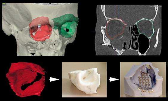
First a digital mold is created, the green intact orbit is auto-segmented and mirrored to represent the right theoretical right side in red. This mold is printed and then titanium is bent to the mold, sterilized and implanted surgically.
Figure 4: Virtual implant fitting.
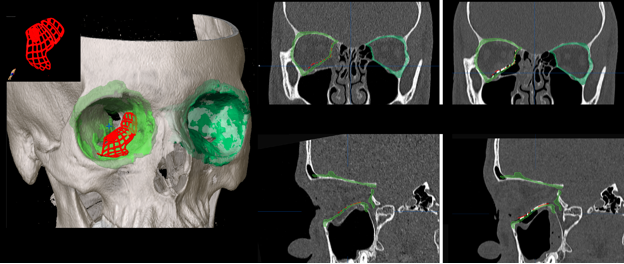
A virtual mold is created using the intact left orbit for a patient with a right medial and floor fracture repair. This is mirrored and superimposed on the right orbit. Avirtual implant representing, in this case, a trimmed, upward-sloping, small-size Synthes preformed anatomic implant, is positioned and demonstrated to match the defect well. The far image shows a post-operative scan which demonstrates accurate positioning relative to the pre-operative goal.
Figure 5: Overview example of a commercial 3-D printed titanium implant.
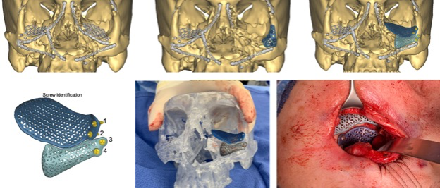
Pre -operatively, the patient had extensive reconstruction. The left orbital volume is insufficiently corrected and the left rim is deficient. The prior implants are subtracted and a new implant for the floor and rim is designed. A small drill guide is also designed (top middle) to aid in positioning. An intraoperative clear acrylic skull is also used to visualize the desired placement.
Figure 6: Commercial patient-specific implant example focusing on drill guide usage.
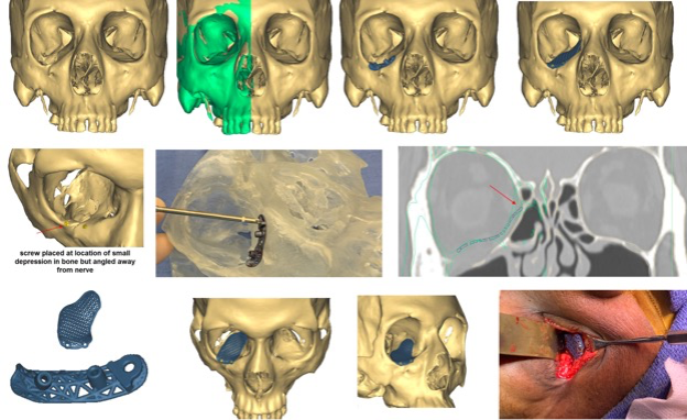
A patient with an old orbital deformity on the right needs a floor implant and there is no posterior ledge for implant positioning. The implant is designed using virtual mirroring of the left orbit onto the right (green). A drill guide is manufactured to help position this implant. Once the screw positions are identified, a guide is manufactured with two tunnels to properly position the angle, depth and location of the screws. A clear acrylic skull demonstrates the fixation of the guide using the fixation hole. Predrilling is performed and the drill guide is removed. The implant is then placed, aligned to the pre-drilled holes and screws are placed.
Figure 7: Workflow for a zygomatic fracture repair using computer-assisted surgery techniques.
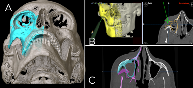
A: Preoperative modeling of the correct zygoma position using the left side as a model (blue). B: Intraoperative navigation, the yellow represents the target zygoma position and the green pointer is used after reduction to verify intraoperative position, C: Post-operative assessment. The purple demonstrates the pre-operative position, the blue the goal position and both are shown on a post-reduction scan.
References
- Aldekhayel S, Aljaaly H, Fouda-Neel O, Shararah A-W, Zaid WS, Gilardino M (2014) Evolving trends in the management of orbital floor fractures. J Craniofac Surg 25:258–261
- Cohen LM, Shaye DA, Yoon MK (2019) Isolated Orbital Floor Fracture Management: A Survey and Comparison of American Oculofacial and Facial Plastic Surgeon Preferences. Craniomaxillofac Trauma Reconstr 12:112–121
- Garibaldi DC, Iliff NT, Grant MP, Merbs SL (2007) Use of porous polyethylene with embedded titanium in orbital reconstruction: a review of 106 patients. Ophthalmic Plast Reconstr Surg 23:439–444
- Insull EA, Hart RH, Sloan BH, Ben-Simon GJ, McNab AA (2013) Use of x-ray film implant for the repair of orbital fractures. Ophthalmic Plast Reconstr Surg 29:393–395
- Lynham AJ, Chapman PJ, Monsour FNT, Snape L, Courtney DJ, Heggie AA, Jones RH, McKellar GM (2004) Management of isolated orbital floor blow-out fractures: a survey of Australian and New Zealand oral and maxillofacial surgeons. Clin Exp Ophthalmol 32:42–45
- Mahoney NR, Peng MY, Merbs SL, Grant MP (2017) Virtual Fitting, Selection, and Cutting of Preformed Anatomic Orbital Implants. Ophthalmic Plast Reconstr Surg 33:196–201
- Metzger MC, Schön R, Weyer N, Rafii A, Gellrich N-C, Schmelzeisen R, Strong BE (2006) Anatomical 3-Dimensional pre-bent titanium implant for orbital floor fractures. Ophthalmology 113:1863–1868
- Greenberg A, Schmelzeisen R. Craniomaxillofacial Reconstructive and Corrective Bone Surgery (2nd Edition). Spinger.
- Peng MY, Merbs SL, Grant MP, Mahoney NR (2017) Orbital fracture repair outcomes with preformed titanium mesh implants and comparison to porous polyethylene coated titanium sheets. J Craniomaxillofac Surg 45:271–274
- Insull EA, Hart RH, Sloan BH, Ben-Simon GH, McNab AA (2013) Use of x-ray film implant for the repair of orbital fractures. Ophthalmic Plastic and Reconstructive Surgery 29(5):393-395.
- Park DJJ, Garibaldi DC, Iliff NT, Grant MP, Merbs SL (2008) Smooth nylon foil (SupraFOIL) orbital implants in orbital fractures: a case series of 181 patients. Ophthalmic Plast Reconstr Surg 24:266–270
